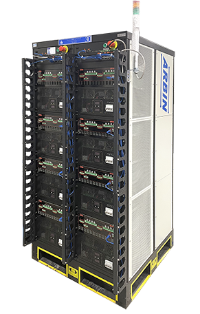
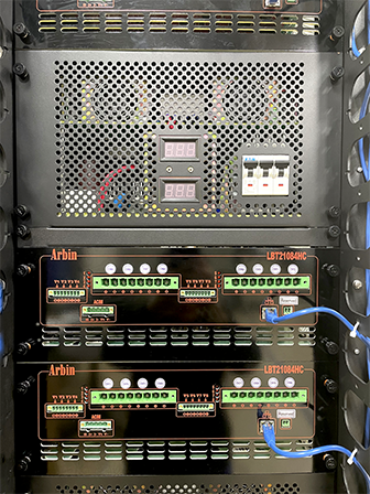
LBT21084HC-5V-10A-64CH
Product Highlights
| Product Series | LBT21 Series |
| Maximum Voltage | 5V |
| Maximum Current | 10A |
| Channel Numbers | 64 |
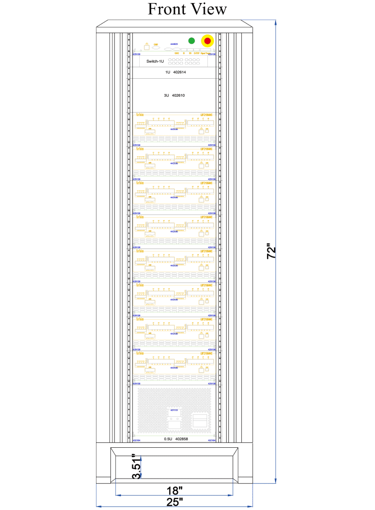
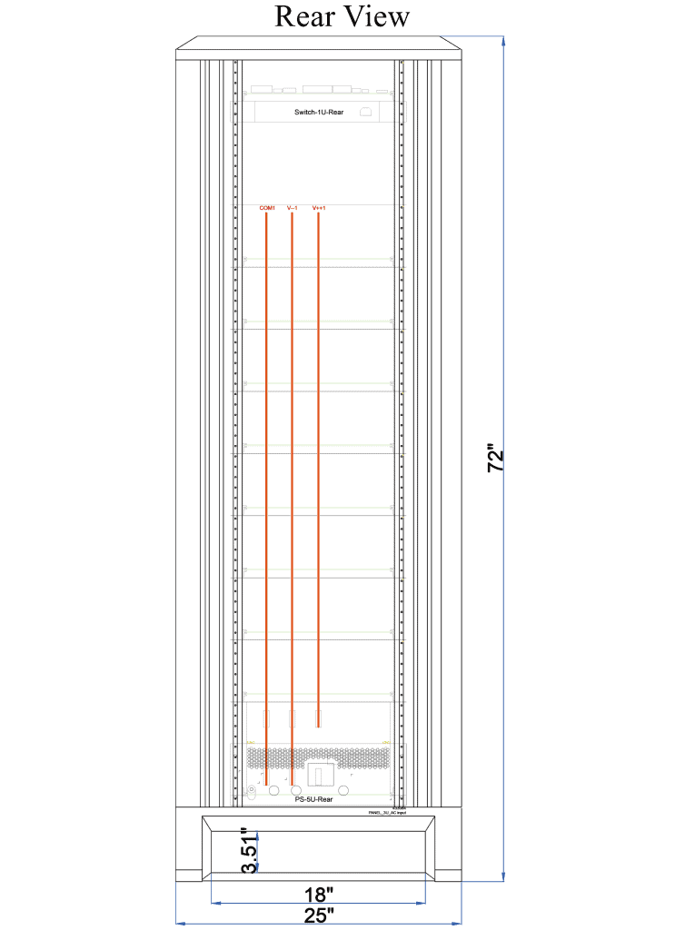
| Chassis Size | 25W45D72H |
Applications
- dQ/dV & Coulombic Efficiency (HPC) Measurements
- Life Cycle Testing
- PITT/GITT
- Symmetric-Cell Testing
- Cyclic and Linear Sweep Voltammetry
- Chronoamperometry
- Chronocoulometry
- Chronopotentiometry
- Multi-Electrode Testing
- EIS (Electrochemical Impedance Spectroscopy)
- Half-Cell Testing and Materials Research
Options and Auxiliaries
- EIS
- Aux Voltage
- Aux Temperature
- MZTC Multi-Chamber
- Chamber Interface
- Analog I/O Digital I/O
- Auto-Calibration
- Uninterrupted Power Supply (UPS)
- Redundant Safety Monitoring System (RSMS)
- 3E Coin Cell Holder
- Battery Holders and Racks
Specifications
| General Description | |||||||||
| System Name | System-LBT21084HC-(-5)~5V-10/0.5/0.02/0.001A-64CH | ||||||||
| Number of Channels | 64 | ||||||||
| Circuit Type | True Bipolar Linear; allows cross-zero linearity. Ensures there is no switching time between charge and discharge within a step; such as performing EV drive Simulations. | ||||||||
| Country of Origin | USA | ||||||||
| Hardware Specification | |||||||||
| Voltage | Ranges | -5V ~ 5V | |||||||
| Measurement Resolution | 24bit | ||||||||
| Measurement Precision | ±0.01% FSR | ||||||||
| Measurement Accuracy | ±0.02% FSR | ||||||||
| Control Resolution | 16bit | ||||||||
| Control Precision | ±0.01% FSR | ||||||||
| Control Accuracy | ±0.02% FSR | ||||||||
| Input Impedance | 10G Ohm | ||||||||
| Voltage Control Mode | Analog | ||||||||
| Hardware Voltage Clamp | No | ||||||||
| Current | Ranges | 10A/500mA/20mA/1mA | |||||||
| Measurement Resolution | 24bit | ||||||||
| Measurement Precision | ±0.01% FSR | ||||||||
| Measurement Accuracy | ±0.02% FSR | ||||||||
| Control Resolution | 16bit | ||||||||
| Control Precision | ±0.01% FSR | ||||||||
| Control Accuracy | ±0.02% FSR | ||||||||
| Minimum V at Max Current | -5V | ||||||||
| Current Rise Time | 400us* Time required for current output to get from 10% to 90% of FSR. |
||||||||
| Max. Continuous Power Output | 50W | ||||||||
| Time | Minimum Step Time | 5ms | |||||||
| Data Logging Rate | 2000 points per second per system | ||||||||
| Measurement Resolution | 100 μs | ||||||||
| Main Chassis | |||||||||
| Chassis Size (W x D x H) | 25'' x 45'' x 72'' | ||||||||
| Cooling method | Air-cooled with built-in variable speed fans; no infrastructure is required. Three feet clearance around chassis. | ||||||||
| Working Temperature Range | 0 ~ 30 °C | ||||||||
| Connection to PC | TCP/IP (Ethernet) | ||||||||
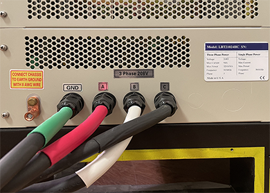
| AC Power Input | Single Phase Requirement | Three Phase Requirement | |||||||
| Voltage | NA / 220 V | 208 / 380 V | |||||||
| Max Power | NA / 2000 W | 8000 / 6000 W | |||||||
| Max Current/Phase | NA / 9 A | 23 / 10 A | |||||||
| Circuit Breaker | NA / 15 A | 30 / 20 A | |||||||
| Frequency | 50/60 Hz | ||||||||
| Built-in Hardware | |||||||||
| Auto-Calibration Interface* | no | ||||||||
| EIS/ACIM Interface** | Yes | ||||||||
| Digital I/O | No | ||||||||
| CAN BUS | Optional | ||||||||
| SMB BUS | No | ||||||||
| Aux Voltage | N/A | ||||||||
| Measurement Accuracy | N/A | ||||||||
| Input Impedance | N/A | ||||||||
| Aux Temperature | N/A | ||||||||
| Temperature Range | N/A | ||||||||
| Measurement Accuracy | N/A | ||||||||
| Data Log | |||||||||
| Minimum log interval per channel | 1ms | ||||||||
| Data Recording Criteria | ΔTime, ΔV, ΔI, ΔPulseCycle | ||||||||
| N/A | |||||||||
| *Autocalibration box is sold separately. | |||||||||
| **EIS testing device is sold separately. | |||||||||
You may consider
Sorry, we couldn't find any posts. Please try a different search.

